-
Home
-
Product
-
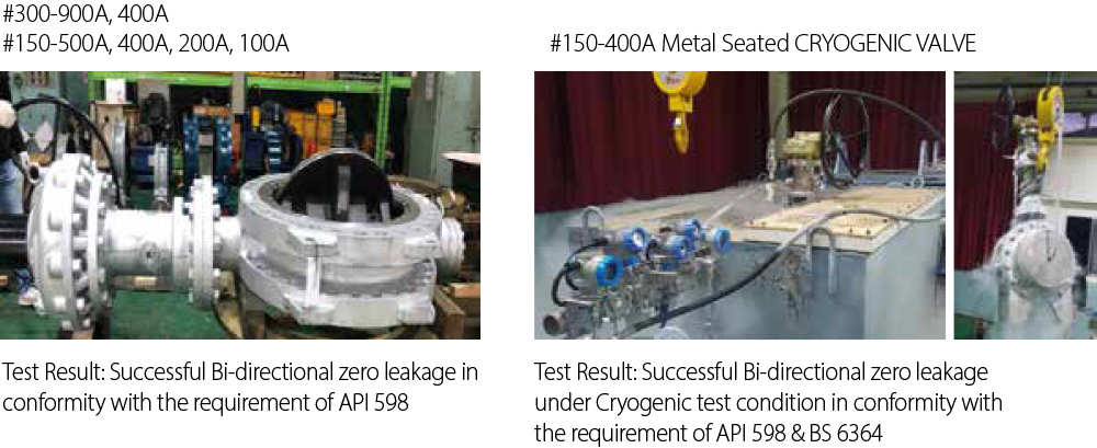
Cryogenic Multi Butterfy Valve
Cryogenic Multi Butterfy Valve
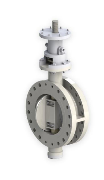
GVK-3000 SERIES
UNIQUE, NEW & WORLD’S FIRST
Linear Lifting STEM/DISC combined with Multiple Offset Design
A new Concept of Innovative Design Valve has been successfully developed and it provides extreme high performance when compared to other type of Metal Seated Butter y Valves including Triple or Quadruple O set Butter y Valve or even Metal Seated Ball Valves.
DESIGN CONCEPT
Linear Lifting Stem/Disc combined with Multiple Offset Design is Unique and the
First in the world. Unique design allows disc to move linearly perpendicular to
body seat against ow direction. It provides ZERO friction on overall surface of
seats when both open & close of the disc during operation which leads to less
torque than ever.
Also, Perfect seat sealing with no seat leakage is well
achieved by exible adjusting way to push the disc against body seat when close
the disc.

KEY FEATURES
- Unique and Innovative Functional Design
- World’s First and New Development
- Multiple Offset Design
- Linear Lifting Stem/Disc Design inducing Zero Friction of Disc & Seat surfaces
- Solid Metal to Metal Seat with hard facing as a basic trim design, Metal to Soft Seat as an option
- Super Fine Seat Face roughness by state-of-the-art machining
- Cutting Edge Seal Technology across the entire seat face
- Replaceable Metal Seat with Retainer
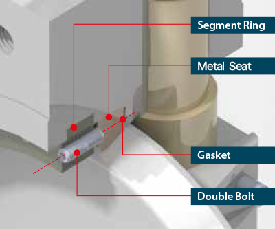
- 01 Retainer Ring features(see below details “A”) SEGMNET RING TYPE Prevents deformation of retainer ring caused by internal pressure of the valve.
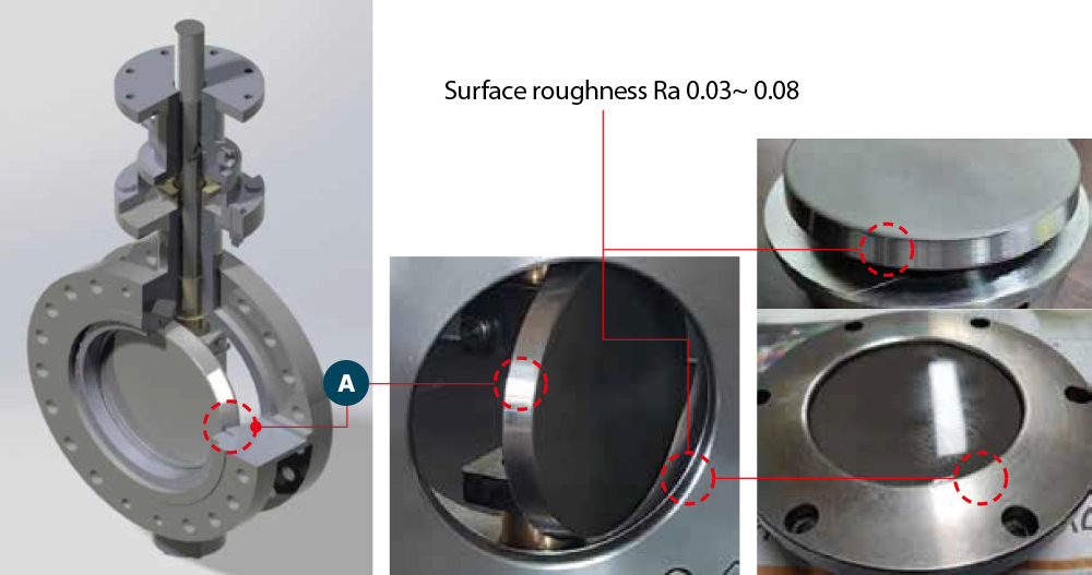
- 02 Disc & Sealing surface roughness TCC coating or Stelite over ray After coating, polishing and lapping treatment surface roughness Ra 0.03~0.08 (see below details “B”)
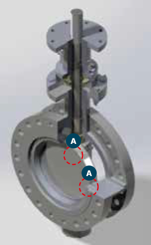
- 03 Disc & Seat surfaces zero friction Solid Metal to Metal Sealing Available. Can be used at high pressure by realizing sealing strength according to the working pressure (see below details “C”)
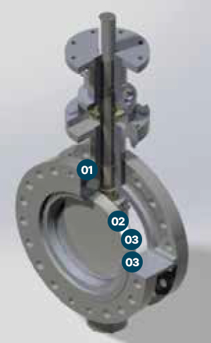
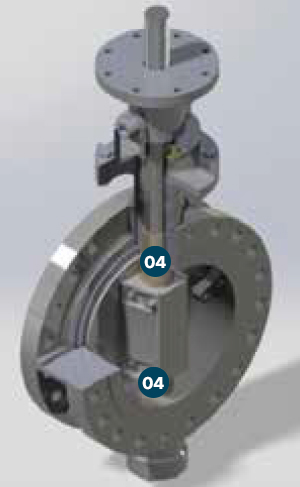
- 04 The valve Disc Position is controlled by upper & lower Bushes Inserted Into the body No disc down by valve operation Can be maintained in initial conditions without change due to valve installation (see below details “D”)
Detail “A”
- No leakage occurs through gasket because the sealing of gasket does not deteriorate even though any forces are exerted on the retainer ring with the disc due to internal pressure
- Any bolt loosening is prevented caused by uid- ow as assembled with double bolt type.
Detail “B”
-
Both Disc & Seat are coated [TCC or Stellite overlay]
- Increasing wear resistance and durability.
Laminated or PTFE seat is available depend on client’s requirement. - After coating, each Disc & Seat is Polished.
-
One-to-one lapping of Disc & Seat after polishing
- Seats surface roughness Ra 0.03 ~ 0.08
-
A
Surface roughness of Disc & Seat surfaces
- Solid TCC Coating and Stellite Overlay
- Perf orm polishing and rapping after coating, and maintaining
Detail “C”
-
Friction free of seating surfaces from before disc rotating
- Interference is eliminated because valve disc moves in a linear before the Open/Close rotation and then performs with rotation acts.
-
ADisc & Seat surfaces zero friction
- Solid Metal to Metal Sealing Basically. Can be used at high pressure by realizing sealing

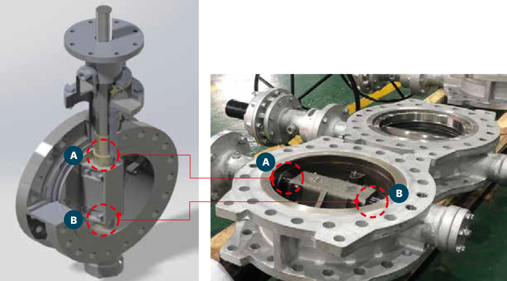
Detail “D” [Disc position controlling by Upper & Lower Bush]
- BothWhen the valve is operated, thrust is generated according to the direction of rotation. At this time, It is a ected by the valve installation direction [Horizontal/Vertical] especially when it is installed Vertically, it is subjected to thrust caused by the disc weight + rotation, the center position of the disc is Changed, and the Sealing point is changed, which often causes leakage. In a typical valve, the disc weight + rotational thrust generated by the operation is designed to be Controlled by the end cover at the bottom of the valve, and when all of these loads are concentrated On the end cover, it is di cult to design with su cient strength because of the narrow space in the Structure of butter y valve.
- Therefore, when the valve is operated after installation, a leakage occurs in the sealing part due to a Change in the disc position, or sometimes a leakage occurs in the end cover position. The upper and lower bushes are inserted into the positions of A and B indicated in the below pictures To control the movement of disc caused by load + rotational thrust when the valve is operated, Thereby maintaining perfect sealing ability.
- The valve disc position is controlled by the Upper and Lower Bush inserted into the Valve body.
- No disc move by valve operation.
- Can be maintained in initial conditions without change due to valve installation.
KEY RESULTS
- Zero Friction for Seating when disc is either being closed or opened
- Eliminating enforced seat contact by linearly lifting stem/disc against body seat
- Intact Seat Face against Severe Service
- Bidirectional Tight shutoff by way of a Unique Flexible Disc Closing Mechanism
KEY RESULTS
- Longer Service Life
- Lower costs for Actuation by Zero Friction & Lower Operating Torque
- Cost Saving by Less Trouble
- Easy opening even after dormant periods
APPLICABLE SERVICES
- Corrosive / Erosive media service including sludge, slurry, oil sand, coal ash, waste water etc
- Severe Service including PP (Propylene Polymer in Vapor/Solid) line, Naptha Cracking line etc
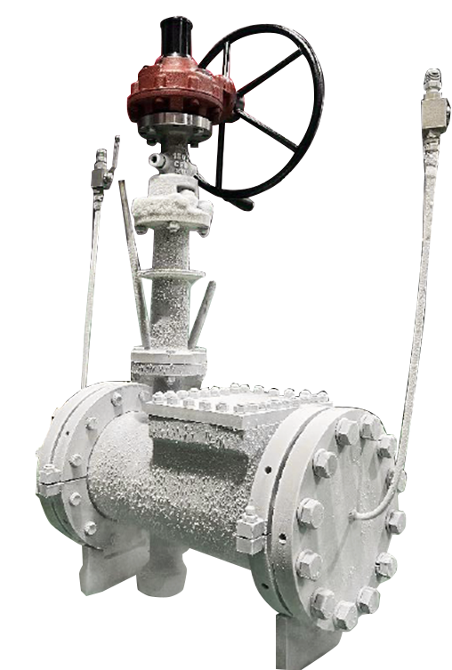
- Cryogenic Service for LNG industry
- High temperature Service
- High Pressure Service
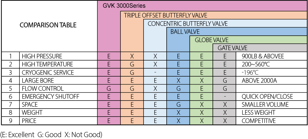
COMPARISON TABLE 1
COMPARISON TABLE 2
| Description | GVK 3000Series | Typical TOBV |
|---|---|---|
| Oset s | Multiple [6 axis] | Triple |
| Stem / Disc Operating | Linear lifting / Rotaing | Rotating |
| Seat ing | Rotating & Linear | Rotating |
| Seat material | Solid metal to metal Metal to soft seat also available |
Metal to laminated seat (Typical) Metal to Metal seat(Special) |
| Impacts(seat damage) the on seat against Flow | NO impacts | Yes, impacts on laminated seat |
| Friction when seating on & off | Zero ftiction - by linearly lifting stem /disc against body seat |
None zero Friction |
| Seat Shut o at full pressure rate for preferred direction | No seat Leakage under metal to metal seat | Within allowable seat Leakage rate(Laminated seat) Hard to reach(metal to metal seat) |
| Seat Shut o at full pressure rate for non-pr eferred direction | No seat Leakage under metal
to metal seat |
Hard to reach(metal to Laminated seat) Hard to reach(metal to metal seat) |
| Bi-dir ectional t ight shut off | Available by way of a Unique exible disc closing Mechanism |
Hard to achieve |
| Seat Surface Hard facing Treatment available | Overlay wedling [Body seat & Disc seat ] TCC, CCC by HVOF |
Overlay wedling [ Body seat or disc seat ] |
| Parts Repair Disc & seat replacement" | Easy & Simple to replace it on site | Hard to replace the disc & Seat on site |
| Seating Tor que[BTO] |
Least Torque than ever without Rubbing on the seat |
Higher Torque than Galaxy due to unavoidable seat rubbing |
| Actuator applicable |
Pneumatic, Electric & Hydraulic with Quarter turn and Linear * |
Pneumatic, Electric & Hydraulic with Quarter turn only |
| Sever e Ser vice applicatio (wear & Tear , erosion) | Suitable with intact metal seat face, linear disc open, seat hard facing |
Diffcult due to laminated seat, rubbing on the seats |
| Cryogenic application |
Bi-directional tight shut o is achievalbe |
Tight shut off is diffcult, especially for non-preferred direction. |
| Sever e Ser vice application (cor rosion) | Suitable with TCC, CCC on the seats | TCC, CCC is not appicable |
| Alternatively replaceable with Ball, Gate, Glove valve | Yes for metal seat | Few |
| Fire safe | Yes with metal to metal seat design | Yes but di cult with laminated seat |
| Fluid control Function for control valve | Yes, Similar to Globe valve | Yes but not much preferred inth industry |
| Budget for the valves in the plant | Lower budget | costly |
Note. * Linear lift ing Stem/Disc can adopt linear actuator which is smaller in size and volume than rotat ing actuators.
DESCRIPTION
- International Standard: API609, JIS F7480, ISO5752, JISB2032, BS5155
- Applicable SIZE Range [Other sizes on request]
- Wafer DN 100 ~ DN 500
- Lug DN 100 ~ DN 800
- Flange DN 100 ~ DN 2000
- Applicable Pressure Range Class 150LB, 300LB, 600LB, 900LB, 1500LB
- Applicable Temperature Range: -196℃ ~ 550℃
- Applicable Flange standard:
- KS/JIS 10K, 16K, 20K, 30K
- ASME B16.5, ASME B16.1 Class 125, 150, 300, 600, 900, 1500, 2500LB
- ISO 7005/EN 1092 / DIN 2501 PN6, PN10, PN16, PN25, PN40
- Operations
- Worm & Bevel Gear operation
- Pneumatic / MOV / Hydraulic ACT.
PRODUCTION
GVK-3000 SERIES
